Services
GEM has expertise in several research areas of engineering importance.
Advanced FEM
- Advanced Meshing and FE Model Generation
- Isogeometric FE Modeling for Solid and Shell Elements
- Multi-path Coupling for Distinct FE Zones
- Extended Finite Element Method for 3D Crack Growth Prediction
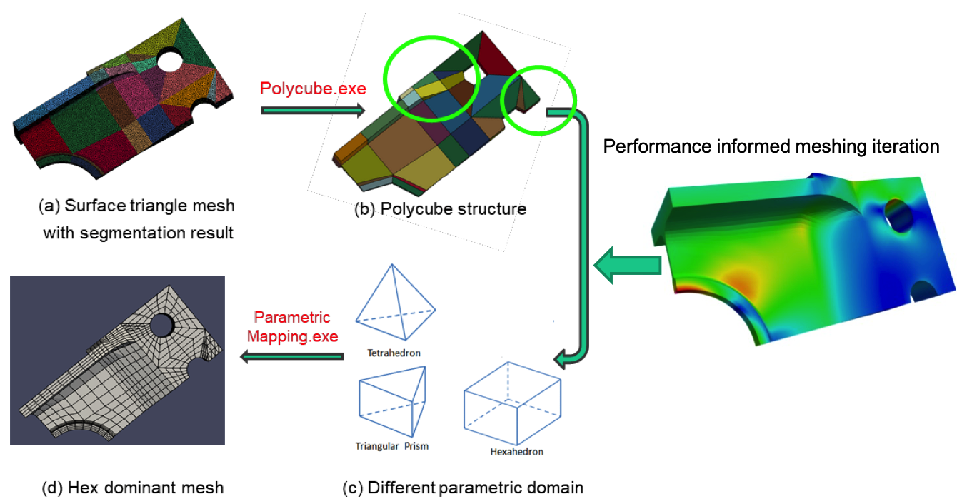
Advanced meshing and FE model generation for complex 3D structures
Under the sponsorship of NAVAIR’s SBIR program, GEM has worked with its members Carnegie Mellon University (CMU) and HexSpline3D, and developed a novel hybrid modeling approach for automatic and interactive mesh generation using predominately hexahedral (Hex) finite elements for naval aviation structures. The hybrid approach consists of a polycube-based approach for automatic partitioning and Hex-dominant mesh generation, generation of tetrahedral (Tet) meshes for space filling and Hex-to-Tet transition zone, and implementation of a vertex-based Tet-merging strategy to further merge suitable Tet into Hex elements.
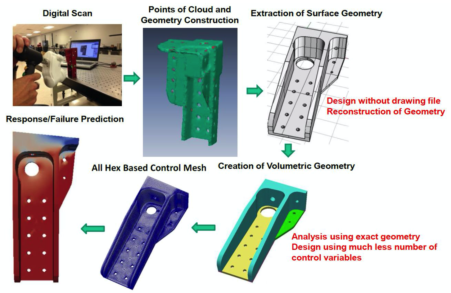
Isogeometric FE Modeling Using Solid and Shell Elements
The advancement of metallic and composite fabrication and manufacturing processes, and the inherent tailorability of materials have pushed the aerospace, automotive, and marine industries to build an advanced structure with a complex geometry using fewer parts. In order to achieve an optimal design and reduce the cost associated with tooling, fabrication, and a test driven certification, a large number of design iterations has to be performed. Conventional finite element models are created from its CAD representations based on their piecewise polynomial approximations. Since software products for CAD and FEA were developed independently, the data from CAD has to be converted into a form to fit the FEM geometry description. Not only does the cost of conversion in terms of processing time and debugging increase as the geometry gets more complicated, but it also introduces approximation errors during the conversion. Such a conversion has to be repeated during a shape optimization process despite the fact that more than 80% of overall analysis time will be spent on the FEA model generation from a given CAD geometry. In order to reduce the burden on the design iteration for performance optimization, it is imperative to create a finite element model from CAD geometry directly. This is where isogeometric analysis (IGA) comes into play. In this context, we have developed a full advanced simulation workflow (see the figure below) and an Abaqus based software toolkit using novel IGA solid and shell elements with analysis-suitable surface and volumetric T-splines.
Specifically, the primary accomplishments of this Phase II Option SBIR program are:
- an automatic analysis-suitable T-spline model generation toolkit for complex surface and volumetric geometries;
- Abaqus-based IGA analysis capabilities using isogeometric solids, Kirchhoff-Love thin shells, and multi-layered continuum shells implemented as UELs; and
- numerical simulation toolkits with GUI (named “IGAFA”) for nonlinear response predictions of composite and metallic structures.
The developed IGAFA toolkit has been applied to a number of real-world engineering applications, and the analysis results have been compared to the results generated by Abaqus, where computational efficiency can be observed. An example of such comparisons is provided in the following.

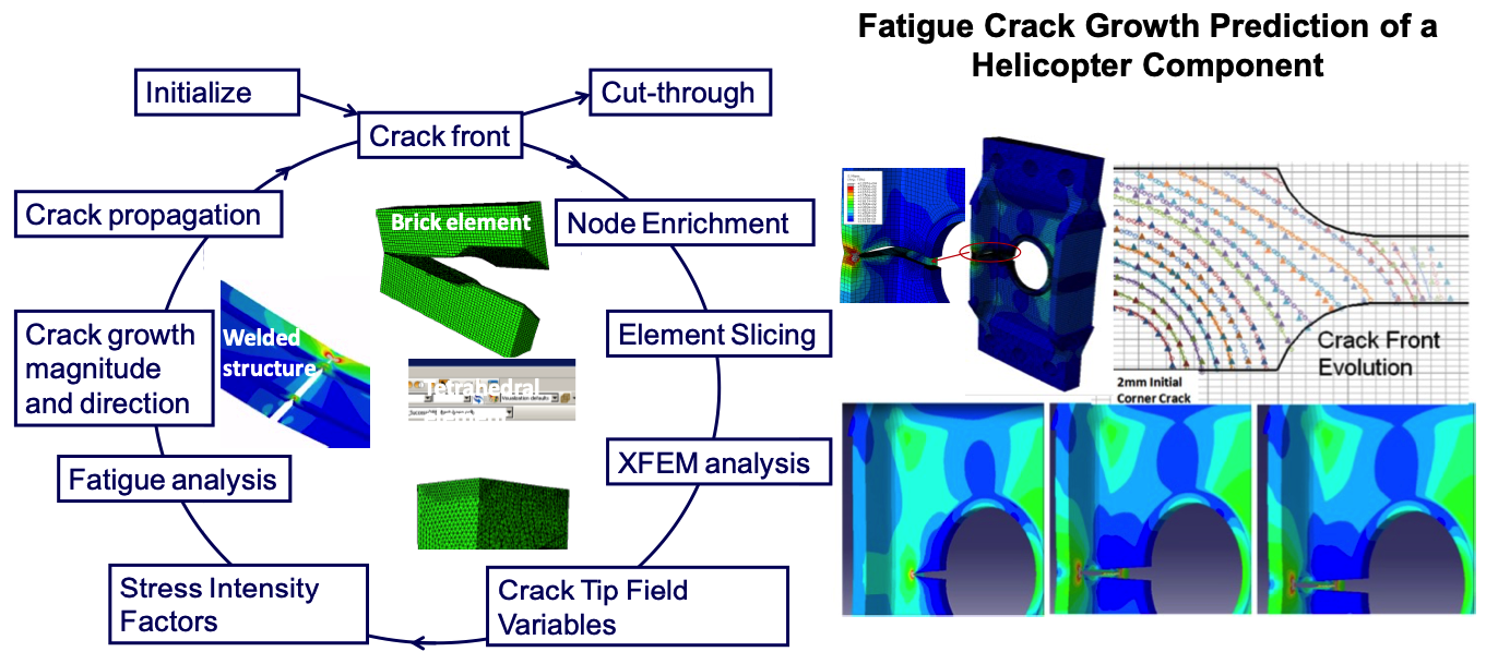
Extended Finite Element Method for 3D Crack Growth Prediction
Under the sponsorship of Navy, NASA, and AFRL, GEM has implemented the extended finite element method for Abaqus’ 3D solid elements. The resulting XFA3D toolkit can be used to simulate a curvilinear crack growth in a metallic structure without re-meshing and can evaluate the residual strength and life of a flawed structural component subjected to monotonic and fatigue loading. A work flow of XFA3D for metallic fatigue crack growth simulation includes the insertion of arbitrary 3D cracks, characterization of cracks via nodal enrichment, extraction of the 3D stress intensity factors at the evolving crack fronts, and prediction of fatigue crack growth and generation of plots after the fatigue analysis.